The Cybersecurity and Infrastructure Security Agency (CISA) has long been recommending using Multi-Factor Authentication (MFA) over just passwords for securing your online presence. The use of MFA is growing beyond just banks using PINs to secure logins and into our everyday lives.
Part of Bandwidth’s portfolio of offerings is 2FA, and today I’ll be discussing how I implemented 2FA into an action I do every single day—locking and unlocking my door. I’ll break down the problem, my attempt at the solution, and how 2FA changed my life! As always, the source code is provided, should you feel inclined to follow along and build your own.
To lock or not to lock
That is indeed a question. How does one secure one’s home? How does one secure anything really? I love the flexibility of giving my babysitter or dog sitter a code and allowing them to come and go as needed.
One thing I’m wary about is what happens if they should accidentally give that code to someone else. But, whether it’s unlocking my door, or unlocking access to my bank account or a health portal, the controlled access that 2FA offers is the same. The solution to my lock concerns, as with any good solution, involves 3D printing, Raspberry Pi, and a servo-motor.
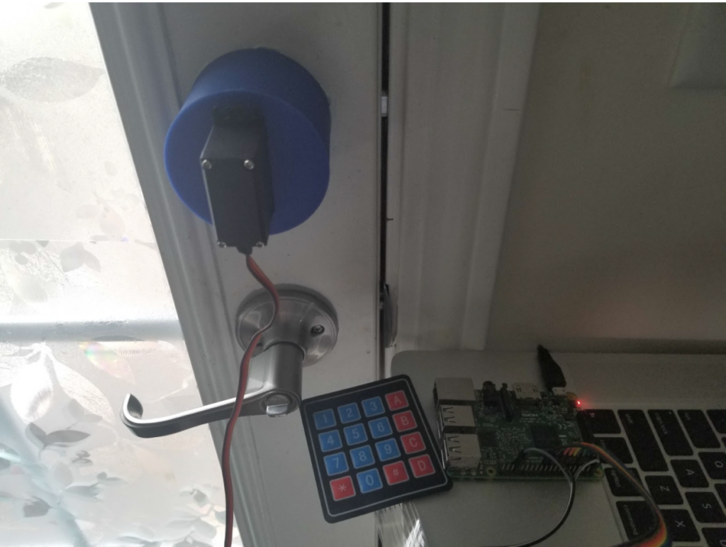
The design is simple, consisting of:
- A Raspberry Pi that acts as the brains
- A servo-motor that turns an existing deadbolt lock
- Some 3D printed housing that makes it all look good (because form is just as important as function).
I’m using an old Pi I have lying around and a 5V servo-motor. I want to draw power from the Pi for the servo and not have to supply another power source or deal with voltage conversion. In general, any servo-motor should do, provided it supplies the adequate amount of torque to rotate your specific deadbolt.
The Input/Output (IO) I am using to interact with the lock is a number pad, but any general IO should suffice.
The nitty gritty
The brains of the matter
The Raspberry Pi is a neat little single-board computer; packing many features of full size computers into a hackable form. For this project, I used a Pi 3 Model B but you could use any other model as well.
I used the GPIO pins on the Pi for both the number pad switch and the servos. I decided to use Node.js because I’ve never used that to control any servos before and wanted to see the options available. I used an open-source GPIO library for the Raspberry Pi instead of hand rolling my own.
The switching of numbers
I used a generic number pad switch, but any general switches will work. Doing so, however, will require a tailored code solution to the input logic to determine button presses. The circuit for the number pad switch is an array of interconnected switches. For my particular model there are four row wires and four column wires.
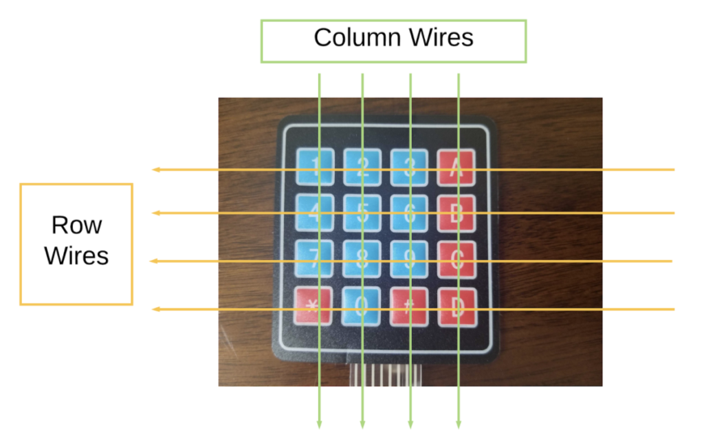
To determine the button being pressed, we set the row wires to be output wires and the column wires to be input wires with a pull down resistor. By switching the row wires on and off one at a time, and testing which column wire is drawn up, that will determine the exact location of the button press.
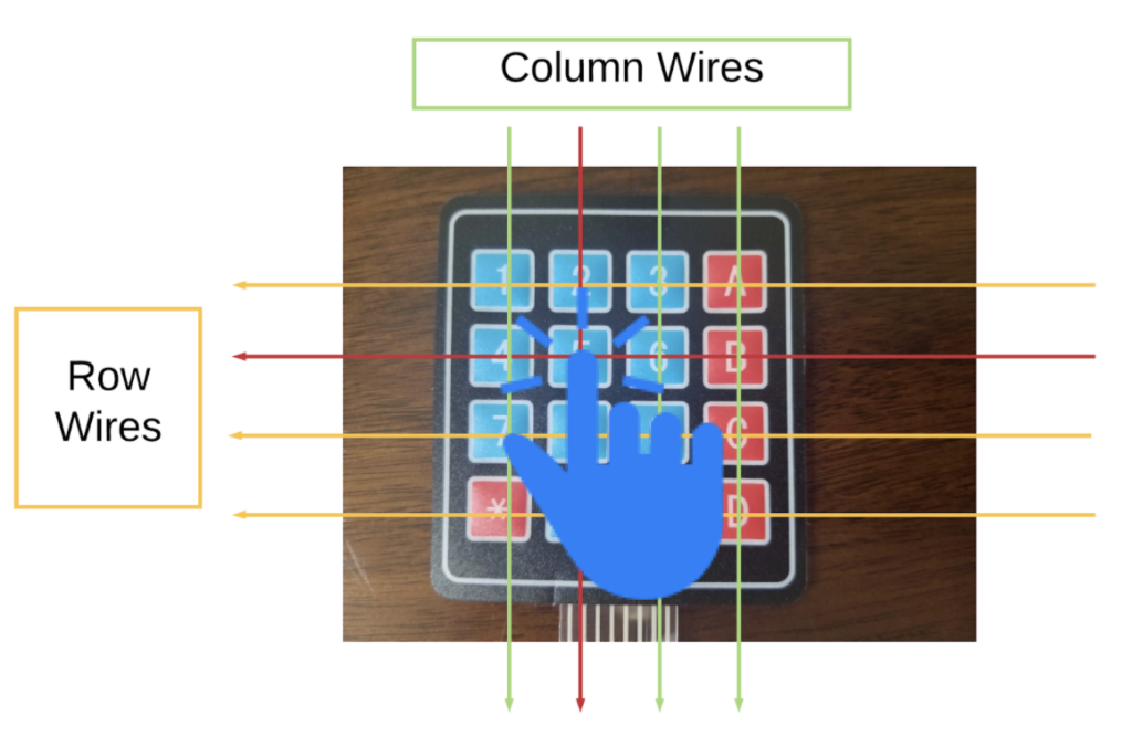
For example, if the number five button is pressed, we first turn row one’s wires on and test if any of the column wire is pulled high. None are, so we know that no button is pressed on the first row. Next, we turn off the first row wire, and turn on the second row. During this run, the second column wire is pulled high and we know it’s the second row and second column, it will map to the number five button.
The following code shows how I implemented the logic to determine which button is pressed.
// GPIO initialization omitted

// Constants for switch layout
const rowArray = [row1, row2, row3, row4];
const buttonArray = [
  ["1", "2", "3", "A"],
  ["4", "5", "6", "B"],
  ["7", "8", "9", "C"],
  ["*", "0", "#", "D"]
];

/**
 * Determine if a column is pulled high by testing each of the column wires.
 */
readColumn = (row, column) => {
  let selectedValue = "";
  row.digitalWrite(1); // turn on row

  if (col1.digitalRead() == 1) {
    console.log(column[0]);
    selectedValue = column[0];
  } else if (col2.digitalRead() == 1) {
    console.log(column[1]);
    selectedValue = column[1];
  } else if (col3.digitalRead() == 1) {
    console.log(column[2]);
    selectedValue = column[2];
  } else if (col4.digitalRead() == 1) {
    console.log(column[3]);
    selectedValue = column[3];
  }

  row.digitalWrite(0); // turn off row
  return selectedValue;
}

/**
 * Read button presses until a desired length has been obtained.
 */
readButtons = async (lengthOfButtonPresses) => {
  let pins = "";

  while (pins.length < lengthOfButtonPresses) {
    for (let i = 0; i < buttonArray.length; i++) {
      pins += readColumn(rowArray[i], buttonArray[i]);
    }
    await sleep(250);
  }
  return pins;
}
As I’m sure you may have noticed, there are more buttons on my number pad switch than I technically need. I decided to hook those up as well if I should need to enter other characters.
The lock turner
The servo I’m using is a MG996R. I selected the MG996R for it’s operating voltage of 4.8V to 6.6V and it’s output torque of over 9kg/cm. This ensures we can operate the servo using the power supplied by the Raspberry Pi, but also produce enough torque (if not more than we need) to rotate most manual deadbolt locks.
// GPIO initialization omitted

// width of PWM in ms
const maxWidth = 2000;
const minWidth = 1600;

openLock = () => {
  console.log("Lock currently close, opening");
  motor.servoWrite(minWidth);
}

closeLock = () => {
  console.log("Lock currently open, closing");
  motor.servoWrite(maxWidth);
}

operateLock = async (doorOperation) => {
  await sleep(1000);
  doorOperation();
  await sleep(1000);
}
To control the servo, I used a pulse width modulation (PWM) wave. Using any GPIO library, there should be an easy interface to control PWMs. In the library I used, it was simply `servoWrite` and the desired pulse width. You may need to play around with the value for the width to determine what values work best for your lock opening state and closing state.
The security factor
Last, but not least, the Two-Factor Authentication offering from Bandwidth. For this application, I used SMS. Bandwidth, however, offers 2FA using either SMS or Voice calls.
Depending on how much you like visitors, feel free to amend this to be as annoying or simple of a process as you want. To get yourself setup for 2FA, please contact your Bandwidth representative! After getting your account and 2FA credentials, here’s the code you need to implement:
const sendSmsCode = async (phoneNumber) => {
   controller = twofactor.APIController;

   return await controller.createMessagingTwoFactor(exampleAppConfig.accountId,
     new twofactor.TwoFactorCodeRequestSchema({
       from: exampleAppConfig.phoneNum,
       to: phoneNumber,
       applicationId: exampleAppConfig.applicationId,
       scope: 'authorization'
     }));
};

const checkCode = async (user) => {
 controller = twofactor.APIController;

 return await controller.createVerifyTwoFactor(exampleAppConfig.accountId,
   new twofactor.TwoFactorVerifyRequestSchema({
     from: exampleAppConfig.phoneNum,
     to: user.phone,
     applicationId: exampleAppConfig.applicationId,
     scope: 'authorization',
     code: user.code
   }));
};
To learn more, check out our Dev Docs
As you can see, the Bandwidth 2FA service is pretty easy to use; two simple endpoints, one to request a new PIN and one to verify the PIN. I’ve configured the 2FA to return a six digit PIN with a three minutes grace window.
These values are easily configurable to suit just about any need. One unique characteristic of Bandwidth’s 2FA offer is the `scope` field. Using the `scope` field, I could configure different actions associated with the 2FA PIN. I could have a PIN for authorization but also one for adding a new user. By having multiple different scopes, it ensures the PIN does not match across different scopes.
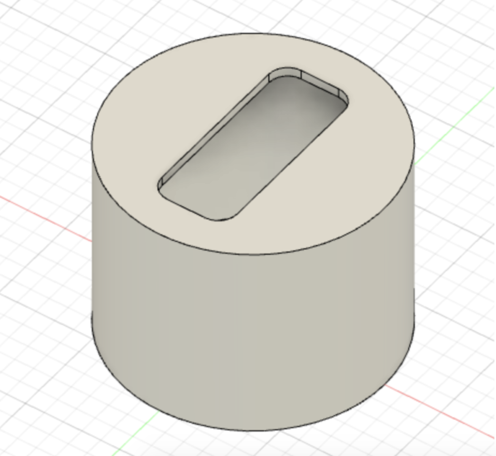
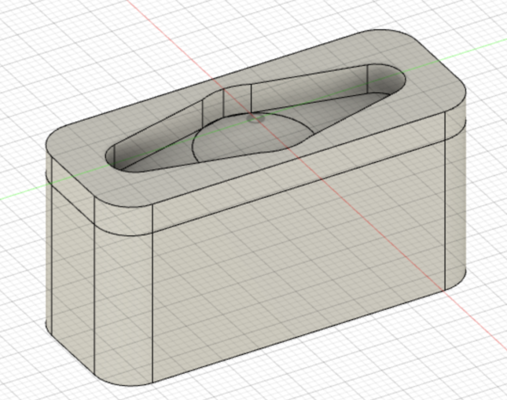
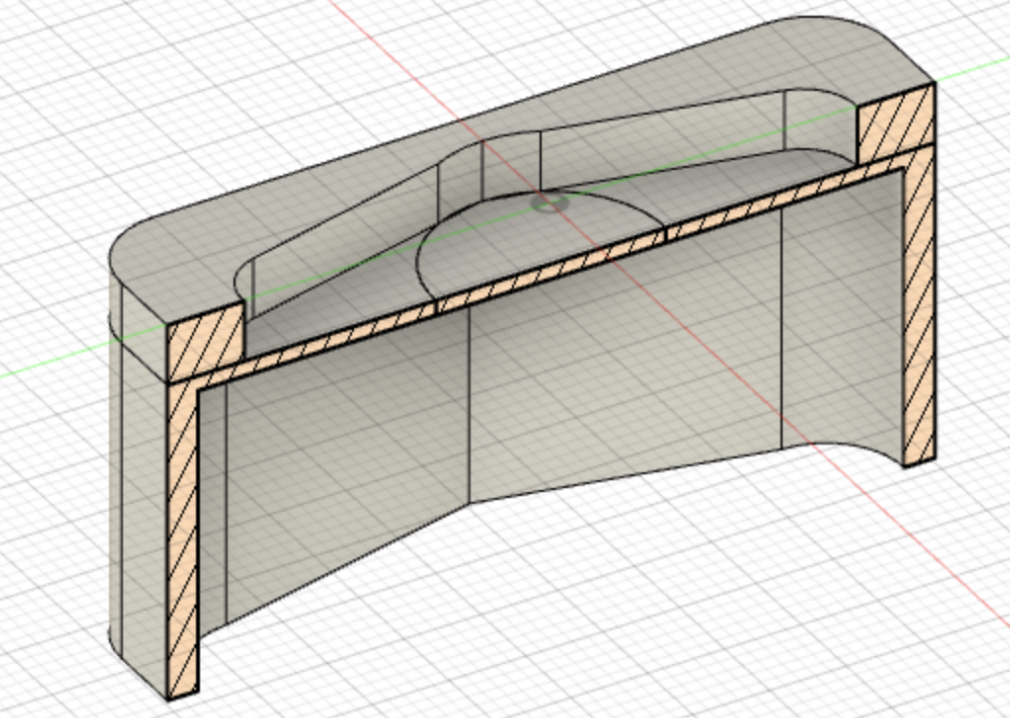
The case of technologies
We can rebuild the lock, we have the technologies; better, stronger, faster! Or something to that effect. I 3D printed an enclosure for the Pi and servo. Of course, it’ll work without it, but let’s face it, I have extra time on my hands due to recent events. I designed my model in Fusion 360, but I’ll publish both the STL file and the Fusion 360 files should anyone feel the need to waste more time redesign it to suit your taste. You may also find the design files in the github repository.
The plug-and-play
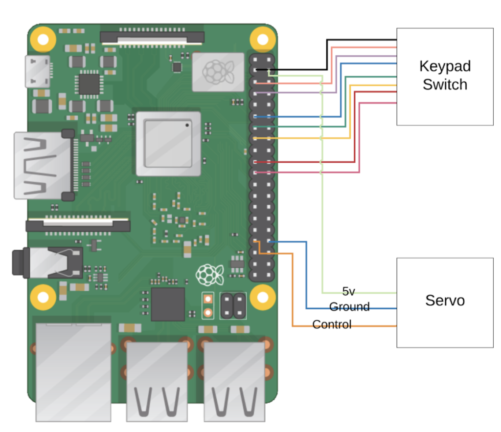
Now we just have to put everything together. Here’s the GPIO pins I’ve decided to use.
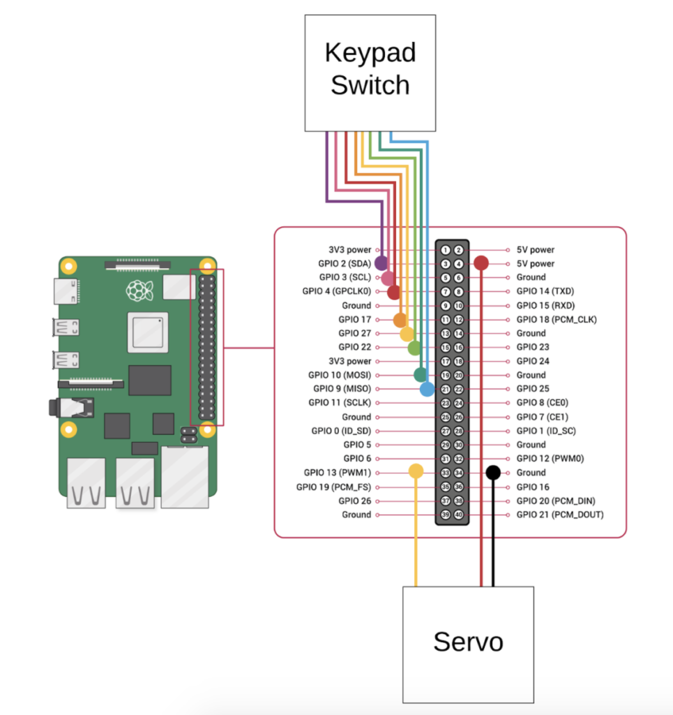
There’s no rhyme or reason as to why I decided to pick these; maybe I like straight lines or random placements. You may choose any GPIO pins, just make sure you update the code to initialize the correct GPIO pins. The full source code can be found here .
Here’s a video of the lock in-action. It is a little difficult to see, but the flow goes:
- User enters door code
- If door code is correct, initiate a 2FA PIN to the user’s phone
- If PIN is correct, open the lock
Should the user enter an incorrect door code or incorrect PIN, the whole process starts over again.
Looking for more comms APIs?
Bandwidth can help. Our enterprise-grade APIs come with 24/7 human support.